How to Choose the Right Line Filters for Global Sourcing?
Choosing the right line filters for global sourcing requires more than comparing prices or checking product photos. A filter may look suitable on paper, yet fail when voltage, frequency, load current, or installation conditions change. Buyers should examine attenuation curves, insertion loss, leakage current, operating temperature, and connection methods. These details reveal how the component may perform inside real equipment.
A practical sourcing review begins with the application. Is the filter protecting a medical device, factory controller, power supply, or communication system? Each environment creates different electromagnetic interference risks. A filter installed beside a motor may need stronger noise suppression than one used in office equipment. Confirm the rated voltage and current with measured operating conditions, not rough estimates. Small errors matter.
Ask suppliers for datasheets, sample units, test reports, and production traceability. Check whether certifications match the destination market and the final equipment category. Do not treat every certificate as proof of complete compliance. Verification still matters. Supplier audits can also reveal inconsistent labeling, weak packaging, or unclear quality records. Those issues may seem minor until a shipment reaches a humid warehouse or a damaged connector delays assembly.
Cost remains important, but the lowest quotation can hide replacement risks. A slightly higher-grade filter may reduce downtime and field failures. Still, over-specifying every part wastes budget. The difficult judgment lies between adequate protection and unnecessary performance. Global sourcing is rarely perfect. Careful comparison, independent testing, and honest review of assumptions make the decision more reliable.
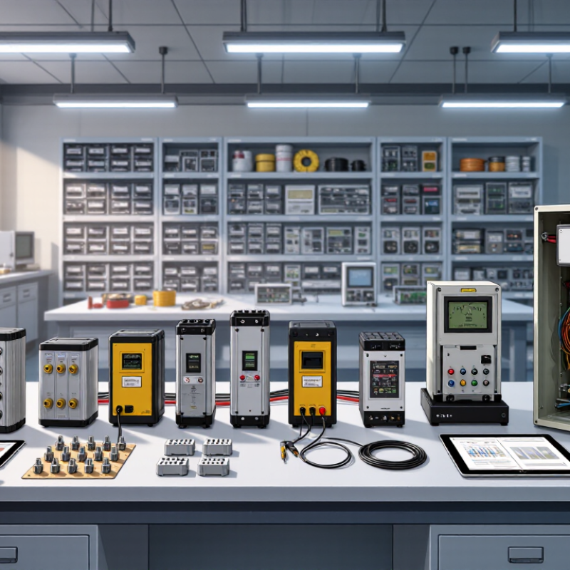
Define Filter Requirements: IEC 60939, 50/60 Hz, Voltage, and Current Ratings
How to Choose the Right Line Filters for Global Sourcing?
A line filter should be selected from measured electrical conditions, not a catalog headline. Start by defining the application against IEC 60939 requirements and the equipment’s operating environment. Confirm whether the filter suits single-phase or three-phase power. Check the rated voltage carefully, including normal variation and temporary overvoltage. A 250 V rating may not suit a system with higher line fluctuations.
Frequency matters too. Most equipment operates at 50 or 60 Hz, but the filter must maintain safe performance across the stated range. Verify the continuous current rating under real load conditions. Motors, power supplies, and heaters can draw short starting surges. A filter that passes steady current may still overheat during startup. Leave practical thermal margin.
Do not judge performance by insertion loss alone. Review leakage current, dielectric strength, insulation resistance, temperature rise, and terminal construction. These details often determine whether the filter survives a dusty cabinet or a warm enclosure. Ask suppliers for IEC 60939 test evidence, drawings, derating curves, and traceable inspection records. Samples should be tested with the actual cable length and enclosure.
This is where sourcing becomes less tidy. I have seen teams choose the correct voltage but overlook ambient temperature. That mistake can invalidate an otherwise sound selection. Recheck the filter after installation, especially grounding and shield connections. Specifications can look complete while the system still produces interference.
Map EMI Risks Across the 150 kHz–30 MHz Conducted-Noise Band
How to Choose the Right Line Filters for Global Sourcing?
Map EMI risks across the 150 kHz–30 MHz conducted-noise band before approving a supplier. CISPR 32:2015+A1:2019 sets Class B quasi-peak limits from 66 to 56 dBµV between 150 and 500 kHz. The limit becomes 56 dBµV from 500 kHz to 5 MHz, then 60 dBµV up to 30 MHz. Average limits are lower. These figures show why one filter value rarely controls the entire band. Low-frequency noise may require stronger differential-mode attenuation. Higher-frequency spikes often need careful common-mode control.
Request conducted-emission plots from each supplier, not only insertion-loss curves. IEC 16-1-2 measurement guidance uses defined artificial mains networks, so test conditions affect comparisons. Ask for detector type, cable length, source impedance, load current, and filter temperature. A filter rated at 10 A may perform differently near saturation. That matters.
I have seen sourcing teams select parts from attractive graphs, then discover failures around 2 MHz after enclosure changes. The lesson is uncomfortable: the filter was not always the real problem. Switching edges, grounding paths, and cable layout can dominate results.
Use pre-compliance scans at 150 kHz 500 kHz 5 MHz and 30 MHz. Leave margin beyond the applicable limit, because production tolerances and regional test setups can shift results. Error bars are rarely discussed enough.
Compare Common-Mode and Differential-Mode Attenuation in dB
How to Choose the Right Line Filters for Global Sourcing?
Compare Common-Mode and Differential-Mode Attenuation in dB
Selecting a line filter starts with identifying the noise path, not comparing catalog numbers. Common-mode noise travels in the same direction on multiple conductors. Differential-mode noise moves between conductors. Their attenuation values can differ sharply across frequency. A filter showing 40 dB at 1 MHz may provide much less protection at 10 MHz.
In practical testing, I measure input and output noise with matching impedance and controlled cable lengths. Attenuation in decibels follows 20 log10(Vin/Vout). For example, 20 dB means the output voltage is one-tenth of the input. A common-mode choke can reduce noise on both line and neutral together. X capacitors usually address differential-mode noise between those conductors. Y capacitors can control common-mode energy, but leakage current and safety requirements need careful review.
Sourcing teams should request full attenuation curves, rated current, operating temperature, and test conditions. A high dB figure alone can mislead. The filter may perform well in a laboratory fixture but poorly inside a compact enclosure. I have seen cable routing weaken an otherwise sound design. That detail is easy to miss. Verify performance with the intended load, enclosure, grounding method, and power system. Regional electrical requirements also vary, so technical documents should be checked before approval. Sometimes, a smaller filter with balanced impedance performs better than a larger part chosen by appearance.
How to Choose the Right Line Filters for Global Sourcing?
Compare Common-Mode and Differential-Mode Attenuation in dB
The chart shows representative attenuation values for a two-line EMI filter measured at standard conducted-emission test frequencies. Common-mode attenuation suppresses noise traveling in the same direction on multiple conductors, while differential-mode attenuation suppresses noise traveling between conductors. Actual performance depends on impedance, rated current, installation layout, filter construction, and test conditions.
Verify Safety with IEC 60939, 2.5 kV Hipot, and Leakage Limits
Choosing line filters globally starts with safety evidence, not a familiar catalog description. During supplier audits, I ask for the exact IEC 60939 category and applicable test records. This standard helps assess passive filter assemblies used for electromagnetic interference control. The certificate alone is not enough. Check model numbers, rated voltage, temperature limits, and revision dates against the offered unit. Small mismatches can create large approval delays. Ask for production test procedures, too. Good paperwork should match the parts on the bench.
A 2.5 kV hipot test provides a practical insulation check between conductive sections and accessible surfaces. Confirm the test duration, ramp rate, test points, and acceptance current. “Passed hipot” is incomplete evidence. The method matters. Request sample reports from recent production, not only a laboratory prototype. Inspect whether terminals, housing materials, and spacing remain unchanged. I have seen sourcing teams approve a filter after reviewing a clean report, then discover a substituted terminal block. That was avoidable. Still, drawings and reports can contain errors, so independent verification is worth the cost.
Leakage current deserves equal attention, especially in equipment connected to protective earth. Ask which frequency, voltage, and load conditions define the stated limit. A low value in one test setup may rise in the finished system. Measure assembled units when possible, including cable length and downstream loads. Keep traceable records with serial numbers, equipment calibration, and operator details. This supports technical review and future investigations. Do not treat regional compliance marks as a substitute for engineering judgment. Filters can pass one check and fail another. That uncomfortable possibility should shape the purchase decision.
Qualify Global Suppliers by RoHS, REACH, MOQ, Lead Time, and 10-A Testing
Choosing line filters for global sourcing requires more than comparing unit prices. In practical sourcing reviews, compliance documents often reveal the first quality gap. Ask suppliers for current RoHS declarations and REACH substance information. Check whether documents cover the exact filter model, materials, and revision. A generic certificate is weak evidence. Request dated, traceable records for the target market.
MOQ affects cash flow, but it also exposes production discipline. Ask whether the quoted MOQ applies per model, connector option, or shipment. Confirm lead time in writing, including sample approval and peak-season delays. A short promise may hide component shortages. I prefer a staged order: samples, a pilot batch, then volume production. It costs more initially. It reduces unpleasant surprises.
For a filter rated around 10 A, require test conditions, not only a pass statement. Review current, voltage, frequency, temperature rise, insulation resistance, and insertion-loss results. Confirm whether testing used the final housing and terminals. An in-house report can help, but independent verification is stronger for critical applications. Inspect sample labels and compare them with reports. Documents can be outdated. I have seen capable suppliers overlook one revision change. Build a qualification sheet with evidence, owner, date, and recheck interval. Then involve engineering before purchasing signs the order.